

 English
 中文简体
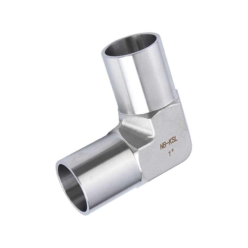


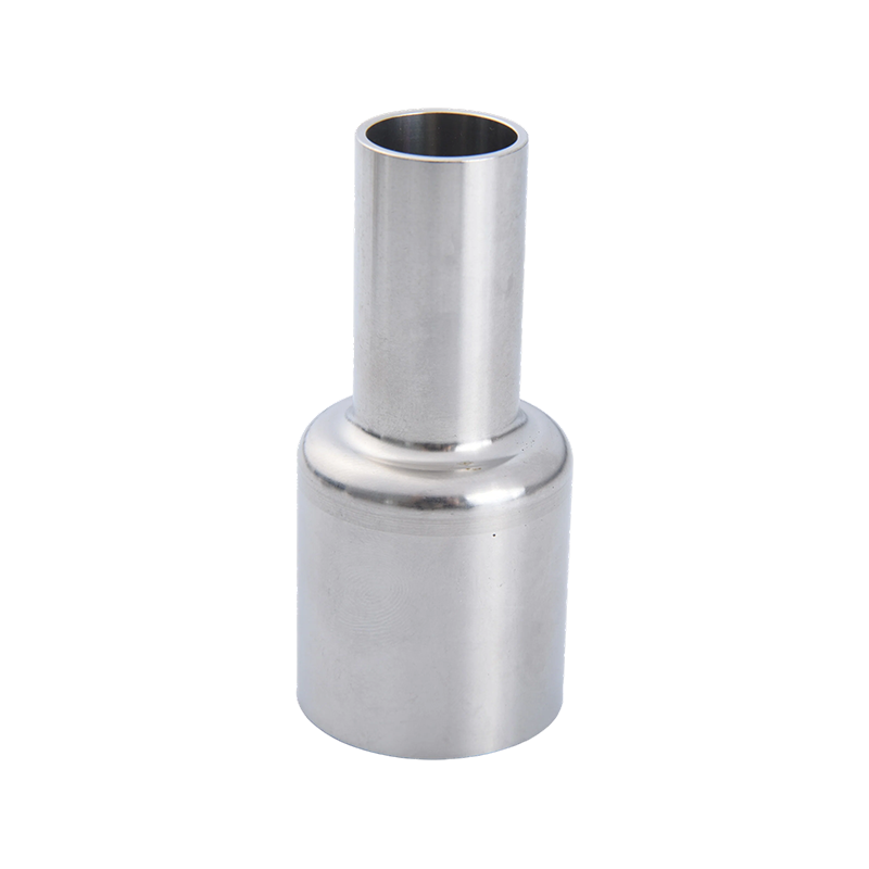
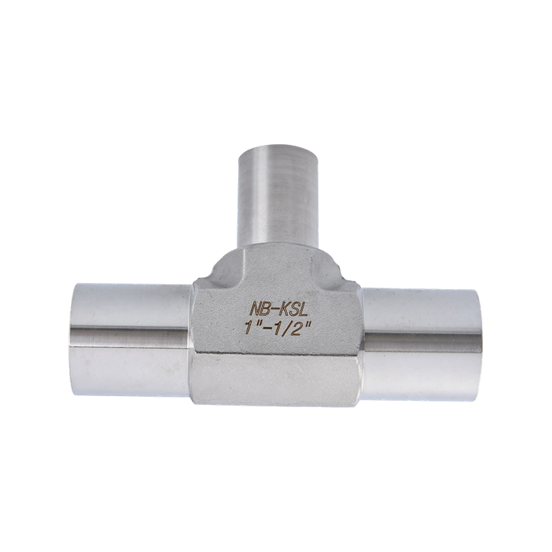
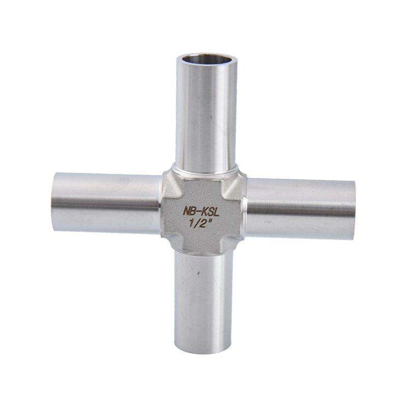
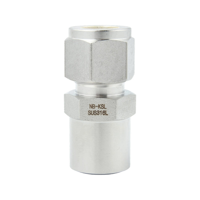
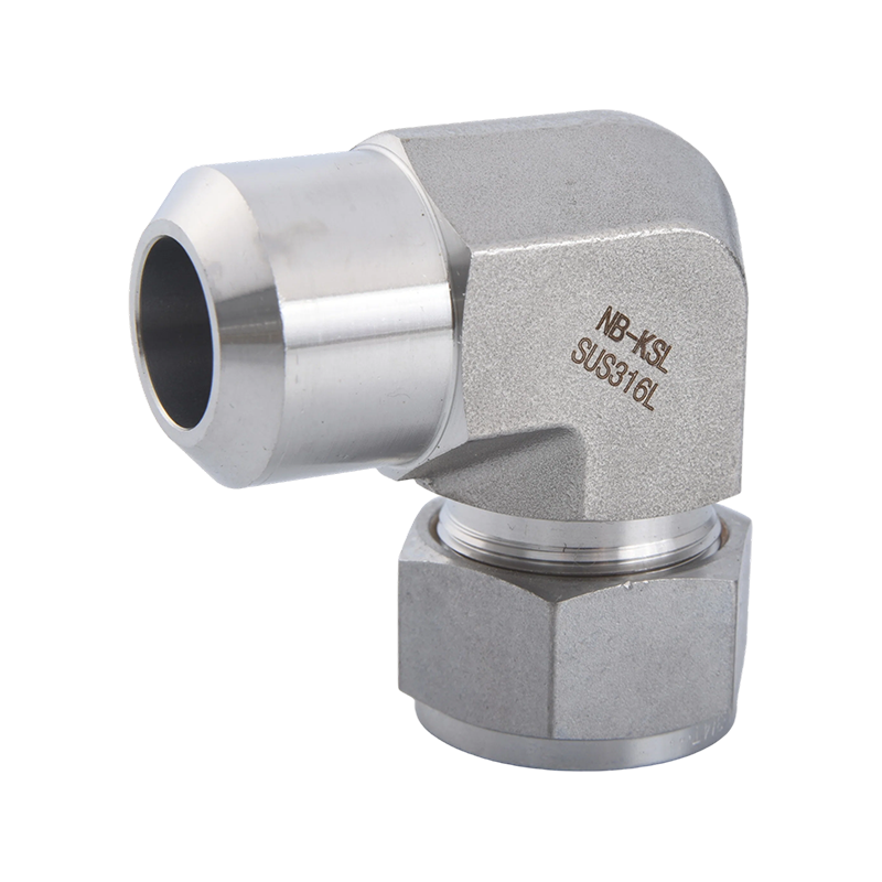
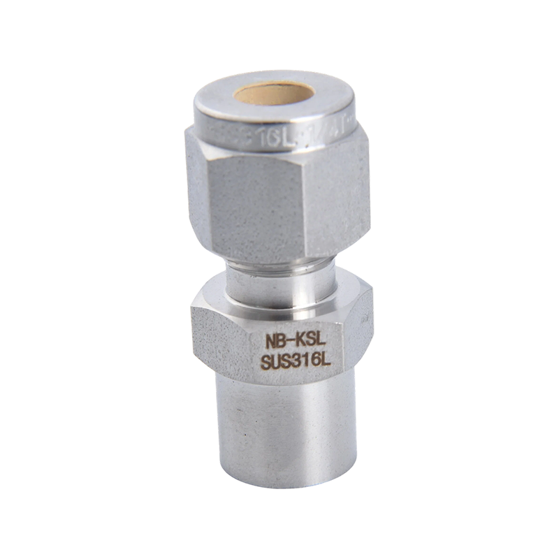


Weld End Preparation and Technical Parameters
| Parameter | Typical Specification |
|---|---|
| End connection | Butt weld (BW), with tube end or pipe end |
| Standard for weld ends | ASME B16.25; EN ISO 9692-1 for weld preparation |
| Bevel angle | 37.5° ± 2.5° for wall thickness above about 4.8 mm |
| Root face (land) | Approx. 1.6 mm ± 0.8 mm |
| Wall thickness | Schedule 5S, 10S, 40S, 80S or customer specified |
| Pipe standard compatibility | ASME B36.19M (stainless), ASME B36.10M, EN 10216 / EN 10217 |
| Body material | CF8, CF8M, CF3M, F304, F316L, duplex |
| Pressure rating | Class 150, 300, 600; PN16 to PN100, subject to wall thickness |
| Seat and seal | RPTFE, PEEK, graphite, metal seat for high-temperature duty |
| Working temperature | -29 °C to +180 °C with PTFE seats; up to 450 °C or more with metal seats and graphite |
| Surface finish | Pickled and passivated; polished or electropolished for hygienic use |
Match the wall thickness. The bore of the weld end should match the pipe inside diameter, so the weld joint has no step that traps liquid or disturbs flow. Because the same nominal size exists in several schedules, please give us the pipe outside diameter and wall thickness, and we will cut the bevel and bore to suit.
For sanitary systems, we supply tube-end valves with plain ends and tangent length for orbital welding, with outside diameters per ASME BPE or DIN 11866.
Specification hint: for best results, tell us the pipe outside diameter, the wall thickness, the material of the pipe and the welding method planned, such as manual TIG or orbital welding. With this information we can choose the bevel, the bore and the end length, and avoid mismatches that only appear during fit-up.
Butt Weld Valve Range and Matching Welded Components
A welded system is designed as a whole. The valve, the pipe, the elbows and the tees must agree in material, wall thickness and weld preparation. We supply butt weld valves with matching butt weld fittings, so the welding crew receives compatible parts, and the weld procedure can be written once for the full line.
| Product | Size Range | Typical Use |
|---|---|---|
| Butt weld ball valves, fully welded or 3-piece | 1/2 inch to 12 inch | Process lines, steam, chemical media |
| Butt weld gate valves | 1/2 inch to 24 inch | High-pressure isolation |
| Butt weld globe valves | 1/2 inch to 12 inch | Flow control and throttling |
| Butt weld check valves | 1/2 inch to 12 inch | Pump discharge and backflow prevention |
| Butt weld strainers | 1/2 inch to 12 inch | Pump and equipment protection |
| Sanitary tube-end valves | 1/2 inch to 4 inch | Pharmaceutical, food, beverage |
| Butt weld fittings | 1/2 inch to 24 inch | Elbows, tees, reducers, caps, per ASME B16.9 |
| Weld neck flanges | 1/2 inch to 24 inch | Transition to flanged equipment |
Why welded connections are chosen
- Leak tightness: a good weld has no gasket and no thread to loosen.
- Strength: joint strength can equal that of the pipe itself.
- Smooth flow: no step or crevice, which suits hygienic and abrasive service.
- Low weight and space: no flange or bolts, so installation is compact.
- Long-term cost: little maintenance of the joint over the life of the system.
The trade-off is that a welded valve cannot be removed without cutting, so we often propose a 3-piece or top-entry design that allows seats and seals to be replaced in line.
Welding End and Piping Standards
Butt weld valves sit at the meeting point between valve standards, pipe standards and welding codes. Each has a say in how the valve should be made and how it should be installed.
| Area | Standard Reference |
|---|---|
| Butt weld end dimensions | ASME B16.25 |
| Weld preparation | EN ISO 9692-1, ASME B16.25 |
| Stainless pipe dimensions | ASME B36.19M, EN 10216-5, EN 10217-7 |
| Carbon and alloy pipe dimensions | ASME B36.10M |
| Butt weld fittings | ASME B16.9, EN 10253-4 |
| Welding procedure qualification | ASME Section IX, EN ISO 15614-1, EN ISO 15609-1 |
| Process piping code | ASME B31.3, ASME B31.1, EN 13480 |
| Pressure-temperature ratings | ASME B16.34, EN 12516 |
| Valve design | ISO 17292, API 600, API 602, API 6D (selected models) |
| Hygienic tube sizes | ASME BPE, DIN 11866 |
Who is responsible for the weld procedure? The installer or contractor is responsible for the welding procedure specification (WPS) and its qualification, since it depends on the pipe, the welding method and the site conditions. We provide chemical composition data, recommended filler metal types and heat input guidance, which your welding engineer can use to prepare the procedure.
If your specification asks for weld end tolerances tighter than ASME B16.25, please tell us in the inquiry.
Dimensional tolerance: weld end tolerances matter because misalignment forces the welder to compensate and may cause a high-low condition at the joint. Our inspection plan checks outside diameter, inside diameter and wall thickness on sampled valves, and the data can be included in the dimensional report that comes with the shipment.
Certificates and Quality Records for Weld End Valves
Welded pipelines are usually part of larger, inspected systems, so each valve may be subject to the project quality plan. We prepare documents that help your welding supervisor and inspector confirm that the valve is compatible with the pipe and the procedure.
- Material certificate: EN 10204 3.1 certificate with chemistry, including carbon and nitrogen contents that influence weldability.
- Weld end inspection report: bevel angle, root face, outside diameter and wall thickness measured on sampled valves.
- Heat treatment record: solution annealing record for castings and forgings.
- PMI report: alloy verification, important for matching filler metal.
- Pressure test report: shell and seat tests per API 598 or EN 12266-1.
- Liquid penetrant or radiographic report: for weld ends or critical bodies, when specified.
- Quality management: ISO 9001 style procedures and batch records.
- CE and PED: available for qualifying models.
Weldability data: we recommend low-carbon grades such as CF3M and F316L for welded installations, because they resist sensitisation in the heat-affected zone. Our certificates show the carbon content so your engineer can confirm the choice.
A sample documentation pack can be sent before order confirmation.
Weld map support: many projects keep a weld map showing every weld, the welder, the date and the heat numbers of the parts joined. We provide heat numbers and valve serial numbers in a simple table that can be imported into your weld map, saving your quality team from copying data by hand. Please send us your preferred column layout and we will follow it.
Traceability for Weld Compatible Material
Welded joints combine two materials: the valve and the pipe. Traceability must prove that the valve material is what it should be, because a small difference in chemistry can change the filler metal, the heat input and the final corrosion behaviour of the joint. We therefore pay close attention to material identity on weld end valves.
- Mill source control: bar, forgings and castings come from approved suppliers with full chemical and mechanical certificates.
- Incoming PMI: chromium, nickel and molybdenum are verified before machining of weld ends.
- Marking: body carries heat number and grade, positioned away from the weld zone so that marking is not lost during welding.
- Weld end machining record: bevel dimensions are inspected on sampled valves and recorded with the heat number.
- Protection: weld ends are covered with caps after machining to avoid damage and contamination.
- Documentation: certificates link heat numbers with valve serial numbers and shipping lots.
| Item | Why It Matters for Welding |
|---|---|
| Carbon content | Lower carbon reduces sensitisation risk |
| Nickel and chromium content | Determines the correct filler metal |
| Molybdenum content | Required to maintain pitting resistance in the weld zone |
| Heat number marking | Supports weld map and as-built records |
If your project includes a weld map, we can supply heat numbers in a format ready for import into your system, so field welders can record which valve went into which line.
Why it matters on site: if a weld later fails inspection, the first question is whether the base material was correct. Having the heat number, the certificate and the PMI report together allows the inspector to answer in minutes, and keeps the investigation focused on the welding itself rather than on questions about the valve. We keep these records for several years and can resend them on request.
Weld End Inspection and Valve Testing Capability
Weld end valves are tested for two things: the valve itself and the quality of the weld preparation. A badly cut bevel makes welding slower, increases the chance of defects and can force the welder to rework the joint on site.
| Test | Method | Frequency |
|---|---|---|
| Bevel angle inspection | Bevel protractor or profile gauge | First article and sampling |
| Root face and wall thickness | Calipers and ultrasonic thickness gauge | First article and sampling |
| Outside and inside diameter | Calipers, bore gauge | Sampling |
| Weld end surface inspection | Visual check, dye penetrant on request | 100% visual |
| Shell test | Hydrostatic at 1.5 times rated pressure | 100% of valves |
| Seat test | Hydrostatic at 1.1 times rated pressure plus air test | 100% of valves |
| PMI | XRF analyser for body and weld ends | Incoming and sampling |
| Radiographic test | On castings or weld ends when specified | On request, third party |
| Heat sink verification | Temperature monitoring of seat area during welding on trial valves | Type test or on request |
Protecting soft seats during welding: PTFE seats begin to deteriorate above about 200 °C. We design fully welded and 3-piece ball valves so that heat can be controlled, and we provide welding guidance: keep the valve in the open position, use low heat input, weld in stages and let the body cool between passes. On request, we can supply valves with removable internals so the seats are installed after welding.
Post-weld inspection: after welding, the joint is normally inspected visually and, depending on the code, by dye penetrant or radiography. A clean, correctly prepared weld end gives better results in these tests, which is why we spend time on bevel accuracy and surface cleanliness before the valve leaves our factory.
Frequently Asked Questions about Butt Weld End Valves
Q: What is the difference between butt weld and socket weld?
A butt weld joins the beveled end of the valve to the beveled end of the pipe, creating a full penetration weld. A socket weld inserts the pipe into a recess in the valve and uses a fillet weld. Butt welds suit larger sizes and higher quality demands, while socket welds suit small bore pipes.
Q: Can ball valves with PTFE seats be welded in the line?
Yes, with care. Keep low heat input, weld in stages and let the valve cool. A 3-piece design or a valve with removable internals is the safest choice.
Q: What bevel angle do you use?
The standard bevel is 37.5° with a root face of about 1.6 mm, in line with ASME B16.25. Other bevel designs, such as J-bevel for thicker walls or special angles, can be made to your specification.
Q: Which grade should I choose for welded stainless valves?
Low-carbon grades such as CF3M and F316L are recommended, because they reduce the risk of sensitisation in the heat-affected zone. Duplex requires special welding procedures.
Q: How do I specify the weld end?
Give the pipe outside diameter, the wall thickness or schedule, and the standard. For example: 2 inch Schedule 40S, bevel to ASME B16.25.
Q: Do I need post-weld treatment?
Austenitic stainless steels do not need post-weld heat treatment. They do benefit from removal of heat tint by pickling and from passivation, to restore corrosion resistance at the weld.
Q: Can butt weld valves be replaced easily?
They have to be cut out and replaced. For that reason, we recommend a flanged or union connection near valves that need frequent maintenance, and butt weld ends where permanent installation is acceptable.
MOQ and Pricing for Butt Weld Valves
Weld end valves are often special by design, because each project has its own pipe size and schedule. We therefore keep minimum quantities flexible and treat weld end preparation as part of the standard offer.
| Item | Typical Terms |
|---|---|
| Sample order | 1 to 3 pieces per model |
| Standard MOQ | 20 to 50 pieces per size and schedule |
| Special weld preparation | Possible; set-up charge may apply for very small quantities |
| Sanitary tube-end valves | MOQ 50 to 100 pieces per size |
| Pricing basis | EXW, FOB Ningbo, CFR or CIF in USD |
| Quote validity | 30 days, adjusted for stainless steel and nickel prices |
| Payment | 30% T/T deposit, 70% before shipment; L/C at sight for approved accounts |
Price factors
- Valve type and size: weld end valves for larger bores are heavier and cost more.
- Material: low-carbon and duplex grades cost more than standard 304.
- Weld end details: special bevels, extended tails and tight tolerances add machining time.
- Seat design: removable internals or metal seats raise the price.
- Testing: radiography and dye penetrant tests are priced separately.
Value note: a butt weld valve may cost a little more than a threaded one, but it removes the cost of flanges, gaskets, bolts and later re-tightening. When the full installed cost is counted, welded connections are often the economical choice for permanent lines.
Choosing the right schedule: using the wrong schedule is a common mistake. A valve prepared for Schedule 10S will not weld cleanly to Schedule 40S pipe without extra machining. Confirm the schedule from the pipe specification or isometric drawings before placing the order, and we will repeat it in our order confirmation for approval.
Lead Time, Customisation, Packaging and Trade Terms
Lead time and stock
Standard butt weld ball valves and check valves in common sizes ship in 20 to 30 days. Special weld preparation, large sizes, duplex or heavily tested valves need 35 to 60 days. If your schedule is tight, tell us the pipe size and schedule early, so machining can be planned in advance.
Customisation
We can customise pipe outside diameter, wall thickness, bevel type, tail length, body material, seat design, stem extension, actuator interface and marking position. We can also provide weld end drawings for approval before production, which prevents misunderstandings.
Packaging for weld end valves
- Plastic or plywood end covers to protect the bevel from damage and contamination
- Valves packed with ball valves in the open position
- Individual wrapping, then cartons or wooden cases depending on weight
- Weld ends kept clear of metal contact to avoid nicks and iron contamination
- Labels with heat number, schedule and weld end standard
Shipping and trade terms
| Term | Details |
|---|---|
| Incoterms | EXW, FOB Ningbo, CFR, CIF, DAP |
| Port | Ningbo-Zhoushan; Shanghai as an alternative |
| Transport | Sea freight, air freight for urgent items, express courier for samples |
| Documents | Invoice, packing list, bill of lading, origin certificate, material and test certificates |
We can ship butt weld valves together with matching pipe fittings and weld neck flanges, which helps you assemble the entire line from one supplier.
Handling at the welding site: keep the end covers on until the moment of welding, clean the bevel with a stainless steel brush and acetone, and avoid contact with carbon steel tools. Good preparation avoids contamination of the weld, and the corrosion problems that follow when iron particles are embedded in the joint.