
Content
A low-pressure alarm on a nitrogen analyzer purge line is rarely caused by the analyzer itself. More often, the real problem is a regulator or valve with a Cv that is too low for the flow demand. The component may look right in the catalog — right size, right material, right pressure rating — but the flow coefficient does not match the application. Cv, or valve flow coefficient, is the standard way to express how much fluid a valve or regulator can pass under defined conditions. Understanding what Cv means, how it is calculated, and how to use it when selecting components prevents this class of sizing error.
Cv is a dimensionless index of flow capacity used across the valve industry. By definition, Cv is the number of US gallons per minute of water at 60°F (16°C) that flows through a fully open valve when a pressure drop of 1 psi is maintained. The reference conditions exist to create a consistent baseline: water at this temperature has a known viscosity and density, and the 1 psi pressure drop is small enough to avoid turbulence that would distort the measurement.
In practical terms, a valve with Cv 4.0 passes 4 gallons of water per minute at 60°F with 1 psi of pressure differential. For gases like nitrogen, the same Cv value provides a starting point, but the calculation must include pressure, temperature, and gas density. The definition assumes a fully open valve because partially open positions have lower Cv values that change with the valve's flow characteristic.
Cv is not a measurement of flow at operating conditions. It is a standardized reference that lets you compare components from different manufacturers. When you convert that reference to your actual fluid, temperature, and pressure drop, you get a predicted flow rate.
For liquid applications, the formula is:
Cv = Q √(SG / ΔP)
Where:
This formula reveals the central trade-off in valve selection: if you have less pressure drop available, you need a higher Cv. A valve with insufficient Cv will consume more pressure than the system can supply, reducing flow below the design target.
Worked example: A chemical dosing system needed to deliver 12 gpm of a fluid with specific gravity 1.05 through a valve with 6 psi available pressure differential.
Cv = 12 × √(1.05 / 6) = 12 × 0.418 = 5.02
A valve with Cv 5.0 would sit exactly at the boundary. Selection guides generally recommend the next size up, so Cv 6–8 provides margin for process fluctuations and valve tolerances.
For the reverse calculation, the formula can be rearranged to predict flow for a known valve: Q = Cv × √(ΔP / SG). If you install a ball valve with Cv 8 in the same line, expected flow at 6 psi would be approximately 8 × √(6 / 1.05) = 8 × 2.39 = 19.1 gpm, which exceeds the design requirement and leaves a safety margin for future capacity.
Gas flow calculations use the same Cv concept but account for gas compressibility. A common simplified formula is:
Cv = Q / (963 × √(ΔP × P2 / (G × T)))
Where Q is the flow in standard cubic feet per hour (SCFH), P2 is the downstream absolute pressure in psia, G is the specific gravity of the gas relative to air, and T is the absolute temperature in degrees Rankine.
For example, a 1/4-inch needle valve rated Cv 0.8 operating with nitrogen (G = 0.967) at 100 psia inlet and 20 psia outlet would pass roughly 1374 SCFH. This shows the sensitivity of gas flow to the absolute pressure ratio and temperature. In practice, most stainless steel valve and regulator manufacturers publish gas flow charts that give Cv values at various inlet pressures and pressure drops. Using these charts is faster and less error-prone than manual calculation.
In metric-based markets, Kv is used in place of Cv. The Kv definition is the flow of water at 20°C in cubic meters per hour through a fully open valve with a pressure drop of 1 bar.
| Parameter | Cv | Kv |
|---|---|---|
| Reference fluid | Water at 60°F (16°C) | Water at 20°C |
| Flow unit | US gallons per minute | Cubic meters per hour |
| Pressure drop | 1 psi | 1 bar |
| Conversion relationship | 1 Cv = 1.156 Kv | 1 Kv = 0.865 Cv |
The most direct consequence of Cv is whether the valve or regulator can deliver the required flow under the available pressure. If Cv is too low, the device restricts the line and creates a flow bottleneck. If Cv is too high, the valve may be oversized, leading to poor control resolution and oscillation.
For control valves, trim size is directly tied to Cv. A given valve body may offer trims rated at different Cv values. Picking a trim that is too small forces the valve to operate near its limit, causing erosion and noise. Picking a trim that is too large reduces control precision because small movements of the stem change the flow by large amounts.
For pressure regulators, Cv determines the maximum flow the regulator can pass while holding its setpoint. An undersized regulator will droop, meaning outlet pressure falls as flow increases. An oversized regulator may hunt or buzz, especially near zero flow. This is one of the reasons stainless steel regulators are preferred in corrosive and high-pressure services, because they maintain their setpoint over long service intervals.
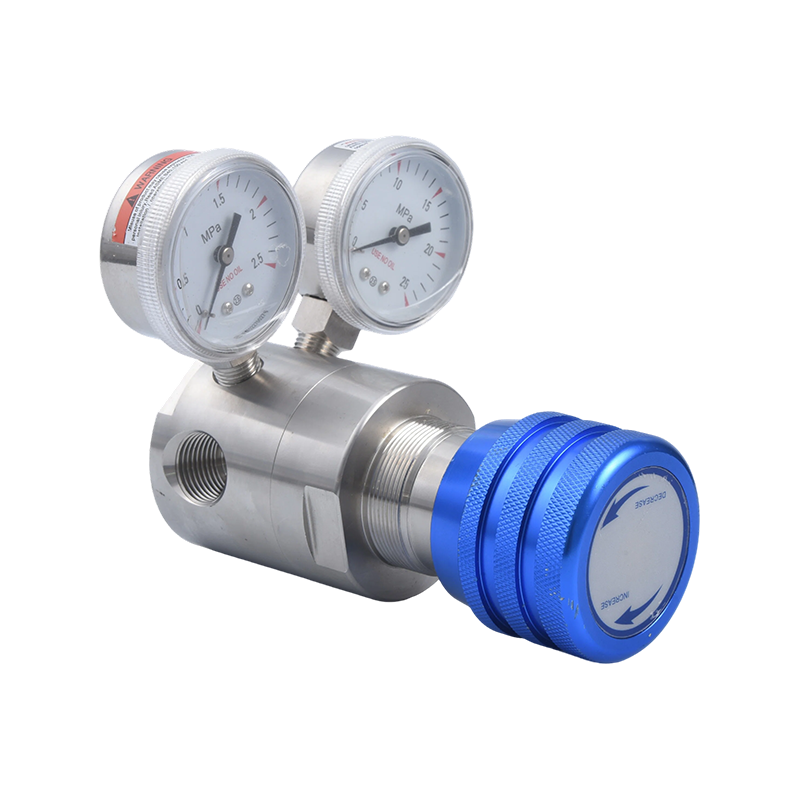
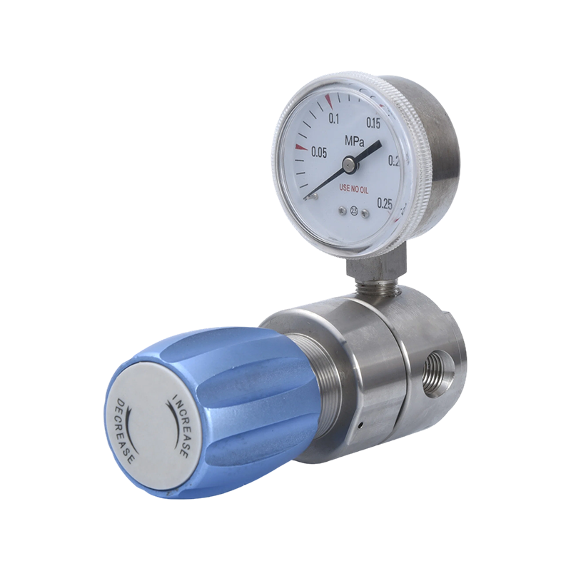 R57 Series Medium-Pressure Regulator for Gas ControlThe R57 regulator provides robust gas pressure control with a 2-inch gauge and safety valve, suited for common industrial gases and environments requiring stable output and easy maintenance.View Product →
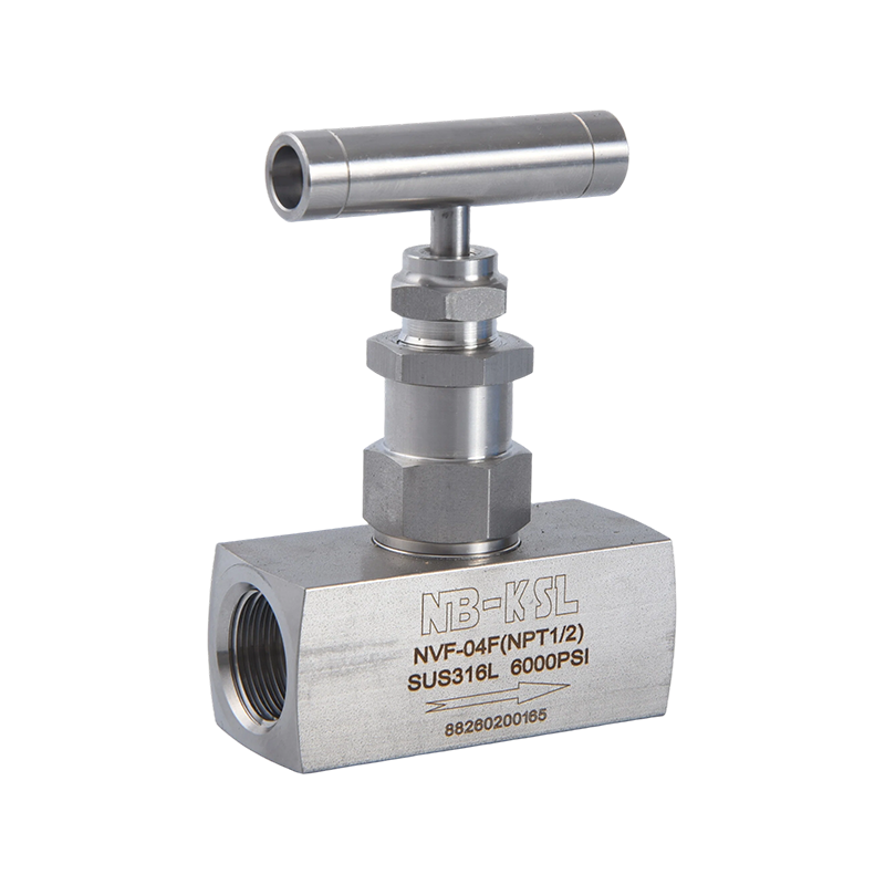
The same logic applies to needle valves used for fine flow adjustment in instrument lines. These valves have low Cv values, often between 0.1 and 1.5, allowing operators to make precise adjustments to small sample flows. Needle valves are installed where the pressure drop is intentionally high to achieve controllability. The relationship between stem turns and Cv is described by the valve's flow characteristic, which is usually documented by the manufacturer.
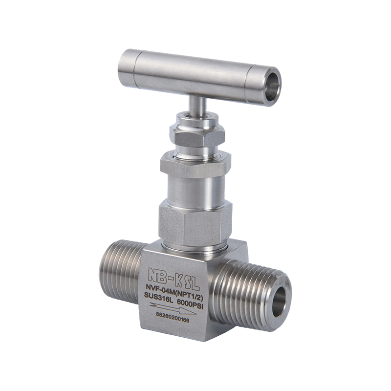 Externally Threaded Needle Valve for Fine Flow AdjustmentThis needle valve enables precise flow regulation in instrument lines, with Cv values typically between 0.1 and 1.5, making it ideal for applications requiring high pressure drop and controllability.View Product →
While the definition of Cv is standardized, actual measured values depend on the manufacturer's test methods and internal valve geometry. A common industry tolerance for published Cv is ±10%. A valve rated Cv 10 could measure anywhere from 9.0 to 11.0. This variation is a natural result of machining tolerances, surface finishes, and wear during testing.
The measurement standard used by manufacturers also matters. In liquid flow testing, the valve is installed in a test rig with a controlled pressure drop, and the measured flow is used to compute Cv. In gas testing, the flow is measured and then converted to a gas-related coefficient. Reputable manufacturers verify the Cv of representative samples before release.
For critical applications, it is good practice to request the tested Cv value from the manufacturer or to verify it on a flow bench. For high-pressure or hydrogen service, suppliers normally provide detailed flow characteristics along with the rated Cv.
The flow coefficient also changes with valve opening. Most valves do not maintain a constant Cv across their stroke. Instead, they follow a characteristic curve — linear, equal percentage, or quick-opening. When a valve needs to operate across a wide range of flows, the characteristic curve matters as much as the maximum Cv.
The practical process for choosing a component is straightforward. Start with the process conditions: required flow, fluid density, and acceptable pressure drop. Calculate Cv using the formula. Then select a component with a rated Cv slightly above the calculated value.
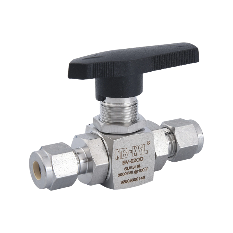
In a 316L stainless steel ball valve for a 1/4-inch instrument line, a Cv of 3 to 5 is common. In a 1/2-inch ball valve, Cv can reach 15 or more. Needle valves in the same line sizes stay far lower. If a ball valve with Cv 15 is placed upstream of a needle valve with Cv 0.5, the needle valve dominates the pressure drop. The ball valve must still be sized so that its own pressure drop at the operating flow is small enough to leave the required differential for the needle valve.
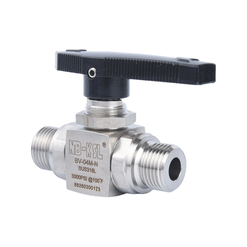 Externally Threaded Straight Ball Valve for Instrument LinesThis ball valve delivers efficient on/off control with a Cv suitable for instrument lines, ensuring minimal pressure drop when paired with downstream needle valves for flow precision.View Product →
When the application involves hydrogen or high-purity gases, the trim, seat material, and internal seal design affect the effective Cv. A small change in seat roughness can change the measured Cv by a few percentage points.
The flow coefficient Cv condenses a large amount of hydraulic information into one number. It tells you whether a valve will pass the right amount of fluid, whether a regulator will hold pressure at the required flow, and whether the trim size of a control valve matches the process. By using the definition, the formula, and the practical margins recommended by manufacturers, you can avoid the most common cause of valve sizing errors: picking a component that fits the pipe but cannot handle the flow.


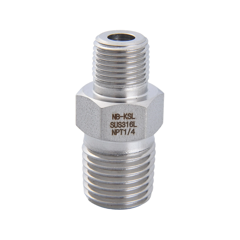
A process engineer once asked me why a new 3/8-inch needle valve could not hold downstream pressure. The valve was not defective; it was oversized. Every small turn of the stem moved more flow than the process needed, and the Cv formula wo...
Quick Answer: Key Specs to Check Before Buying For most instrumentation and process applications, a 316 stainless steel needle valve rated for 6,000 psi with a 1/4 in. to 1/2 in. NPT or tube-fitting connection covers the majority of genera...
If you need tube fittings that resist corrosion, handle high pressure, and last decades with minimal maintenance, stainless steel tube fittings are the right choice for the vast majority of industrial, chemical, and food-grade applications....
What Stainless Steel Needle Valves Are and How They Work A needle valve controls flow through a small-bore orifice by advancing or retracting a tapered needle-shaped stem into and out of a precision-machined seat. As the handwheel or actua...
 1 Zhongxin Yungu Zone D Building 1, Jiangkou Street, Fenghua District, Ningbo City, Zhejiang Province, China
 +86-574-88561893 / +86-15057497901
 Copyright © Ningbo Keshengli Stainless Steel Valve Co., Ltd. Rights Reserved.
Wholesale Stainless Steel Fittings & Valves Manufacturers
Copyright © Ningbo Keshengli Stainless Steel Valve Co., Ltd. Rights Reserved.
Wholesale Stainless Steel Fittings & Valves Manufacturers



 English
 中文简体
中文简体