

 English
 中文简体


Lockable Handle Types and Technical Parameters
| Handle Type | How It Locks | Typical Use |
|---|---|---|
| Lever handle with locking plate | A hole in the handle lines up with a hole in the stop plate in the open or closed position; a padlock passes through both | General isolation, lockout and tagout |
| Latch handle | A spring latch holds the handle in position, with a padlock hole for added locking | Frequent operation, prevents accidental movement |
| Oval or T-handle with lock | Handle locks on a stop pin, with padlock hole | Compact valves and panels |
| Key lock handle | Keyed lock built into the handle or valve body | Restricted access, one key per operator |
| Car seal or wire seal handle | Hole for a one-time tamper-evident seal | Valves locked open or closed with audit trail |
| Insulated handle with lock | Handle with plastic sleeve and locking plate | Hot lines and cold lines |
| Gear operator with lock | Hole in handwheel or gearbox cover | Large valves |
Typical valve parameters
| Parameter | Typical Specification |
|---|---|
| Body material | CF8, CF8M, CF3M (A351); F304, F316L (A182) |
| Handle and stop plate | 304 stainless steel, thick enough to resist bending; handle sleeve in plastic |
| Padlock hole | Typically 8 to 10 mm, suitable for standard padlock shackles up to about 8 mm |
| Lock positions | Open, closed, or both; some designs with intermediate positions |
| Size range | 1/4 inch to 8 inch (DN8 to DN200) |
| Pressure rating | 1000 WOG, PN16, PN40, Class 150, Class 300 |
| End connections | NPT, BSP, socket weld, butt weld, flanged, tri-clamp |
| Working temperature | -20 °C to +180 °C with soft seats |
| Seat | PTFE, RPTFE, PEEK; metal seat on request |
Check your padlock. The hole must be big enough for the padlock shackle, and the shackle should fit snugly without bending. Some plants use multiple padlocks on one valve, for several workers, with a hasp or lockout device. Tell us the shackle diameter, and we will make sure the holes suit your locks.
Lockable Valve Range and Lockout Accessories
Lockable handles are available across many valve types and sizes. For existing valves that do not have lock holes, we can also supply retrofit lockout devices and handle kits, so that a plant can upgrade without replacing the valves.
| Product | Size Range | Locking Feature |
|---|---|---|
| 2-piece ball valve, lockable lever | 1/4 inch to 4 inch | Padlock hole in open and closed position |
| 3-piece ball valve, lockable lever | 1/4 inch to 4 inch | Padlock hole, stop plate |
| Flanged ball valve, lockable | 1/2 inch to 8 inch | Padlock hole, gear operator option |
| Sanitary tri-clamp valve, lockable | 1/2 inch to 4 inch | Latch handle with padlock hole |
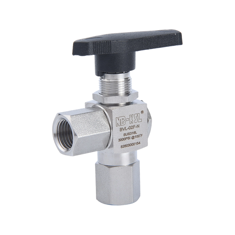
| Three-way ball valve, lockable | 1/4 inch to 2 inch | Locks in selected flow positions |
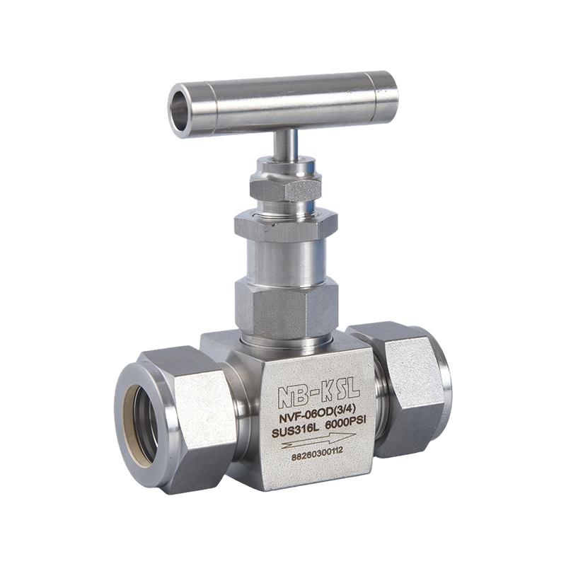
| Needle valve with locking knob | 1/8 inch to 1/2 inch | Locking cap or set screw |
| Butterfly valve, lockable notch plate | DN40 to DN200 | Locks in multiple positions |
| Gear operated valve, lockable | DN200 and larger | Padlock on handwheel or gearbox |
| Retrofit lockout kits | Matched to valve | Clamp-on or bolt-on lockout devices |
Where lockable valves are used
- Maintenance lockout: isolating pumps, tanks, heat exchangers and process equipment during repairs.
- Safety systems: fire water supply valves locked open, relief valve isolation valves locked open.
- Gas and fuel supply: fuel lines to burners and engines, where accidental closing is dangerous.
- Chemical dosing: setting points that should not be altered by unauthorised persons.
- Public and commercial buildings: boilers, gas meters, water main isolation valves.
If your plant uses coloured or numbered locks, tell us, and we can supply matching colour handles or tags.
Safety Standards and Practices Behind Lockable Valves
Lockable handles are not described in one single standard, since they support safety procedures that are set by regulations, company policies and valve design standards. Understanding the references helps you specify a valve that fits your procedure.
| Area | Standard or Regulation |
|---|---|
| Lockout and tagout, United States | OSHA 29 CFR 1910.147 (control of hazardous energy) |
| Lockout practice, general | ANSI/ASSE Z244.1 |
| Machinery safety, isolation of energy | ISO 14118, EN ISO 14118 (prevention of unexpected start-up) |
| General machinery safety principles | ISO 12100 |
| Valve locking in design standards | API 608, API 6D and ISO 17292 refer to locking devices on request |
| Relief system isolation, lock or seal open | API 520, API 521 recommendations and company practices |
| Pressure and temperature ratings | ASME B16.34 |
| Ball valve design | ISO 17292, MSS SP-110, API 608 |
| Testing | API 598, ISO 5208 |
Locking is a procedure, not only a part. A lockable valve supports a lockout and tagout system, but the safety depends on training, written procedures, personal locks and tags. We supply the hardware, and the plant must supply the procedure. If you need help with specification wording, we can share typical wording used by customers.
Locked open versus locked closed. A valve in a fire water line or under a relief device should be locked open, while an isolation valve during maintenance is locked closed. The valve must therefore have lock positions in both states, which many simple lever handles lack.
Reference note: safety regulations differ between countries and between industries, and company procedures often go further than the law. Tell us the procedure or specification your site follows, for example lock positions, number of padlocks per valve or colour codes, and we will check that our handle arrangement suits it.
Documents and Evidence for Lockable Valves
Safety managers and inspectors will want to see that the locking feature has been designed and tested, and that the valve itself is suitable for the duty. We provide documents that cover both.
- Valve data sheet: showing lock positions, hole sizes, handle type and stop plate arrangement.
- Drawing of the locking arrangement: with dimensions of the padlock hole and the handle.
- Handle strength statement or test report: showing that the stop plate withstands the specified torque or force when locked.
- Material certificate: EN 10204 3.1 for body, ball, stem, handle and stop plate, where requested.
- Pressure test report: shell and seat test per API 598 or EN 12266-1.
- Fire safe and anti-static documents: for valves in fuel or gas service, where applicable.
- Quality management: ISO 9001 style system and batch records.
- Third-party inspection: SGS, BV, TUV or the buyer's inspector can check lock positions and strength.
Test the lock under load. A locked handle that bends or breaks under a strong push gives a false sense of safety. Our strength check applies a defined torque to the locked handle and looks for deformation. We can show the test or provide a report for the design.
Sample data sheets and drawings can be sent before the order is confirmed.
Audit tip: keep the data sheet, the lock arrangement drawing and the strength statement in your safety file for each valve type. Safety auditors often ask how the locking function was verified, and having these documents ready shows that locked valves are chosen with care and not only fitted with a padlock hole.
Traceability and Marking for Locked Valves
In a plant with hundreds of locked valves, each one needs a tag, a record and a logic. The valve must be easy to identify, and the lock position must be clear to every worker. Our marking and records help the plant keep an accurate inventory of locked valves.
- Valve identification: body heat number, size, rating and material are marked on the valve.
- Tag numbers: laser marked or on stainless steel tags attached to the handle or body, as agreed with the customer.
- Position marking: clear OPEN and CLOSED indication on the handle or stop plate, with colour option.
- Lock record: valve list showing which positions can be locked and the lock hole size.
- Strength record: handle and stop plate material and thickness recorded for each lot.
- Packing record: cartons labelled with item, size and lot, linked to the packing list.
| Item | Record | Purpose |
|---|---|---|
| Body | Heat number and certificate | Proof of grade |
| Handle and stop plate | Material and thickness | Resistance to defeat of the lock |
| Lock hole | Diameter and position | Fit with padlock |
| Tag | Number and position | Link to plant lockout list |
| Valve | Serial or lot number | Link to test reports |
We can also provide a spreadsheet of tag numbers, valve sizes and lock positions, which your safety team can import into its lockout procedure.
Why tags help: in a large plant, the lockout list names each valve by its tag number, and a worker in a hurry looks for that number on the valve. Clear, durable tags attached at the factory avoid handwritten labels that fade, and make the lockout procedure faster and safer for everyone involved.
Testing the Locking Function and the Valve
Testing a lockable valve involves two things: the normal valve tests, and checks of the locking feature. The second set is often overlooked, but it is what gives the user confidence that the valve can be locked and will stay that way.
| Test | Method | Frequency |
|---|---|---|
| Shell and seat test | Hydrostatic and air tests per API 598 or EN 12266-1 | 100% of valves |
| Lock hole alignment check | Standard padlock inserted in open and closed positions | 100% of valves |
| Handle strength test | Defined torque applied to locked handle, then checked for deformation | Type test and sampling |
| Stop plate check | Visual and dimensional check of plate thickness and attachment | 100% visual, sampling dimension |
| Operating torque | Torque tester at the stem | Sampling |
| Handle fit | Check of stem square and handle nut tightness | 100% of valves |
| PMI | XRF analyser for body, ball and stem | Incoming and sampling |
| Cycle test | Repeated operation with locking and unlocking | Type test |
Alignment is the key. If the hole in the handle does not line up with the hole in the stop plate when the valve is fully open or closed, the lock will not fit. This can happen when the handle is mounted at the wrong angle or the stem has a tolerance problem. We check alignment on every valve with a real padlock before shipping.
Customers are welcome to witness the test, and we can send a short video of the locking check on request.
Reading the strength test: the test applies a torque larger than a normal person could apply by hand, while the lock is in place, then checks for permanent deformation of the plate and handle. If the lock still fits and the valve still turns freely afterwards, the design is judged adequate for the intended duty.
Frequently Asked Questions about Lockable Handle Valves
Q: What is lockout and tagout?
It is a safety procedure used to make sure that equipment is isolated from energy sources and cannot be started during maintenance. A lock and a tag are applied to the isolation point, such as a valve.
Q: Can a lockable valve be locked in both open and closed positions?
Yes, if the handle and stop plate have holes for both. Please specify both positions when ordering, since some basic designs only lock closed.
Q: What size of padlock fits?
Most lockable handles accept padlock shackles up to about 8 mm in diameter. Tell us the diameter of your lock, and we will confirm the hole size.
Q: Can I add a lock to a valve I already have?
Often yes, with clamp-on or bolt-on lockout devices, or a replacement handle with a locking plate. We can supply kits for many valve types.
Q: What is a car seal?
A car seal is a numbered single-use seal that shows if a valve has been moved. It does not stop movement, but it provides evidence, and it is used for valves that must stay open or closed.
Q: Can lockable valves also be automated?
Yes, but lockout practice for automated valves involves energy isolation of the actuator, such as air and power, as well as locking of the valve. We can discuss suitable designs.
Q: Are lockable handles stainless steel?
The handle and stop plate are normally stainless steel for strength and corrosion resistance, with plastic sleeves for comfort and insulation.
MOQ and Pricing for Lockable Handle Valves
Lockable handles add a small cost to a standard valve. The price depends on handle type, size and the number of lock positions, and we show these clearly in the quotation.
| Item | Typical Terms |
|---|---|
| Sample order | 1 to 5 pieces per model |
| Standard MOQ | 50 to 100 pieces per size for standard lockable valves |
| Custom handle or special lock | 200 pieces or more, depending on tooling |
| Retrofit lockout kits | MOQ 50 to 100 pieces per type |
| Pricing basis | EXW, FOB Ningbo, CFR or CIF in USD |
| Quote validity | 30 days, adjusted for stainless steel price changes |
| Payment | 30% T/T deposit, 70% before shipment; L/C at sight for approved accounts |
What affects the price
- Handle design: latch handles and key lock handles cost more than simple lockable levers.
- Material and thickness: thicker stop plates and stainless handles add cost.
- Size and valve type: base price depends on valve size and construction.
- Lock positions: locking in open and closed positions needs a more complex stop plate.
- Marking and colour: laser marking, tags and coloured sleeves add small costs.
Safety is worth it. The price of a lockable handle is small compared with the cost of an accident or a shutdown caused by an operator opening a wrong valve. We suggest specifying lockable handles on all isolation valves for equipment that is regularly maintained.
Ordering advice: list which positions on your site need to be locked open and which locked closed, and choose lockable handles for all of them in one order. A uniform design across the plant makes training simpler, and spare handles are easier to stock for maintenance teams.
Lead Time, Customisation, Packaging and Trade Terms
Lead time and stock
Standard lockable ball valves in popular sizes ship in 10 to 20 days. Flanged valves, special handles and valves with key locks usually need 25 to 40 days. If you need a special padlock hole size or special marking, tell us early.
Customisation
We can customise lock positions, hole diameter, handle shape and length, handle colour, stop plate thickness, key lock type, tag and marking, valve body and end connection. For large projects, we can match your existing lock and tag system.
Packaging
- Individual packing with handle attached, or handle packed separately to avoid damage
- Valves packed in the open or half-open position
- Inner boxes with dividers and export cartons on pallets
- Labels with size, rating, material and lock positions
- Neutral or customer-branded packaging on request
Shipping and trade terms
| Term | Details |
|---|---|
| Incoterms | EXW, FOB Ningbo, CFR, CIF, DAP |
| Port | Ningbo-Zhoushan; Shanghai as an alternative |
| Transport | Sea freight, air freight for urgent items, express courier for samples |
| Documents | Invoice, packing list, bill of lading, origin certificate, material and test certificates |
We can ship lockable valves together with spare handles, padlocks or tags if you want to supply a complete lockout set to your end customer.
Installation advice: mount the handle at the correct angle so that the lock holes align when the valve is fully open or closed, tighten the handle nut firmly, and test the lock with a real padlock before putting the valve into service. This five-minute check prevents unpleasant surprises during the first maintenance shutdown.